
 THE
R/C STICK II
THE
R/C STICK II
This page last updated 10/26/96
Click Here to Skip Down to the Latest
Information...
This article explains how to convert a Conquest T4NBF 4 channel FM transmitter into an IBM PC compatible joystick with rudder and throttle. It should also work with an Attack 4 AM Transmitter as the cases are identical, although a switch will have to be installed for use as the joystick trigger as the Attack 4 does not already have one. When I wrote the original construction article on the R/C Stick a year and a half ago, the response was tremendous. Since then I've learned a few new things. The original R/C Stick only worked with Flight Unlimited and Microsoft Flight Simulator 5.0 (FS5), but the R/C Stick II will work with any flight sim that uses a joystick, and if properly setup, should calibrate correctly using the standard calibration in the game. You can also easily convert your original R/C Stick into an R/C Stick II just by replacing the potentiometers (pots) (yeah, you gotta grind new shafts again, sorry). The only difference between the two is that the R/C Stick II uses 1 meg-ohm pots, allowing nearly the same resistance range as a standard joystick's 150 K-ohm pots, because of the smaller angle of the throw in an R/C transmitter's joysticks. What took me a lot of experimention to nail down was the exact (and very critical) angle that the pots have to be installed in, in order to work properly. There was also a mistake in my original wiring diagrams: one of the pins I designated as +5 volts is used for the Midi interface in Sound Blaster compatible sound cards.
Hobby stores in my area are selling the T4NBL without a crystal, battery or antenna for 20 bucks as a buddy box. They're also available mail-order from Frank's Hobby House at (602) 992-3495. I think Tower carries them also, and there are usually others selling them advertising in RCM magazine. As I said earlier, this should also work with an Attack 4 transmitter - if you've been in the hobby as long as I have, you may even have a spare one lying around somewhere. This may work with other transmitters, but you're on your own there. Be aware that some transmitters (such as the Futaba FG series) use separate potentiometers for the stick axis and it's trim, and these won't work. You must also have a game port on your computer that has provisions for two sticks on one port connector. Some older cards have two separate jacks, one for each stick. Some of the multi function cards, and game ports on sound cards support only one stick period. I strongly recommend a speed adjustable game port like the CH Products Game Port III as it will work more precisely and will allow you to set the port for the speed of your computer. Remember, if you add another game port card, you must disable any others already in the computer or they'll interfere with each other.
The R/C Stick II works with any software that supports a standard IBM-PC compatible joystick. No special provisions are necessary. If you'll be using the R/C Stick II with Flight Unlimited from Looking Glass Software, I strongly recommend that you install the version 2.01 update patch. The original version of FU has a bug that does not properly calibrate the joystick on some machines. The update patch fixes this as well as several other problems. It's available on Compuserve from the Game Publisher's A Forum in the Looking Glass section, and is called FUPAT201.EXE.
Getting Started:
First off, READ THIS ARTICLE THROUGH IN IT'S ENTIRETY BEFORE
DOING ANY WORK! This project is not for the faint of heart.
You should have electronics experience, know how to solder wires,
and have some mechanical talent (if you've been into aeromodeling
for a few years, this is probably no problem). Both chassis
ground for the computer and the 5 volt power supply run through
the joystick cable. THE GROUND AND + 5 VOLT LINES MUST NEVER
TOUCH EACH OTHER WHILE THIS JOYSTICK IS PLUGGED INTO YOUR
COMPUTER WITH THE POWER ON! YOU MUST BE VERY CAREFUL TO CONNECT
EVERYTHING PROPERLY SO AS NOT TO DAMAGE YOUR COMPUTER'S POWER
SUPPLY OR THE JOYSTICK CARD! The instructions and diagrams
included in this article are accurate to the best of my ability,
but people can make mistakes. Double check all the wiring before
connecting anything! You've been warned. Any damage to your
computer is not my responsibility.
What's Required:
Still with me? Tools required are a Volt-Ohm Meter (VOM) or
continuity tester, a soldering iron or very low power soldering
gun, a Dremel tool with a fiberglass reinforced cutting wheel,
and some fine grit sand paper. You may be able to do without the
Dremel and use a hacksaw and a metal file, but as a lesson in
patience, it'll have few equals. A solder sucker would be handy
too, but it's not necessary. Parts required are four 1 Meg-Ohm
(1,000,000 ohms) LINEAR taper potentiometers (pots), a can of
contact or tuner cleaner spray (NOT WD-40 or any other
lubricant), a roll of electrical tape and some Vaseline or light
grease. Make sure to get linear taper pots -- audio taper won't
work. You can purchase the pots at Radio Shack (part number
271-211) for about a buck and a half a piece, along with the
tuner cleaner. Buy five or six pots, you'll probably screw up the
first one or two -- there is a learning curve to this.
You'll also need a joystick extension cable you can cannibalize.
I found a six footer at CompUSA for eight dollars.
Disassembling the Transmitter:
Remove all the electronics from the transmitter except for the
trainer switch (we'll wire the trainer switch as the trigger
button). Loosen the antenna bolt and pull out the whole main
circuit board. Unplug the trainer jack from the circuit board
(it's not soldered) and just wrap the cable up and tuck it out of
the way with some tape, or cut the wires off at the jack.
Unsolder the four joystick pots from the small PC boards attached
to them. Then remove the two joystick assemblies by removing the
four screws holding each one in place (on the face of the
transmitter) and pull them out. Don't mix them up. You must also
remove the meter and power switch to make enough room for the
larger pots we'll be installing. Loosen the nut holding the eye
hole where you clip on your neck strap and the fake chrome
plastic face will come off, allowing you to remove the meter and
the switch. Unsolder the switch from the small PC board it's
attached to so it can be pulled out the front, you can just cut
the wires on the meter. Also, remove the charge jack -- we'll use
this hole to lead out the joystick cable. Save all the
electronics: now you have a complete set of spare parts for a
T4NBL Transmitter!
We have to replace the pots because the ones in the radio are 5 K Ohm. Yes, I know the Radio Shack pots are bigger. I looked everywhere for the smaller ones, even specialty electronics distributors with no luck. Don't worry, it's a tight fit, but they work. Examine the joystick assemblies carefully. They're not as complicated as they look. Check out the throttle, it's by far the simpler one. Go ahead and remove the thin spring steel strip that provides the friction for the throttle stick. Only disassemble one pot assembly at a time, so that if you have a problem putting it back together, you can compare it to the others. The pots are attached to the assembly by a brass bushing, but is free to turn within it to allow the pot to rotate slightly in either direction for trim adjustment. The two oblong cams attach the pot to the trim tab, so that when you adjust the trim, all you're doing is turning the entire pot, changing the center position. Remove the two small screws that hold the side of the joystick in place, and the side will come free with the pot and the trim cams attached. The pot's shaft is attached to the joystick assembly with a snug fit, so don't be afraid to wiggle a bit, just don't force it. Pry it loose with a small screwdriver if you have to, very carefully. As you can see, there's another cam on the inside connected to a spring and a tension adjustment screw. This cam is what allows the stick to spring back to center (the throttle doesn't have one). Loosen the tension screw first so the spring won't fly across the room when you remove it (Yup, it happened to me!). Work over a clean uncluttered surface so you won't misplace any stray parts. Remove the spring, cam, and tension screw/block. Keep all these parts in a baggie so you won't lose them. To remove the pot, use a vice grip or pliers to (carefully) loosen the brass bushing from the inside face of the assembly. Try not to chew it up. Once it's loose, you can probably unscrew it by hand. The pot will come off along with the two oblong cams. Notice how the parts go together. Clever these Japanese.
Modifying the New Pots:
Put all the parts away in a baggie except for the pot. Notice the
shape of it's shaft. It's semi-circular with a flat notch on one
side, and a whole lot shorter that the one you bought. You must
Dremel the shafts on the new pots to the same specifications. Cut
the shaft on the new pot with the Dremel cutting wheel to the
same length as the old one. Measure from where the shaft exits
the threaded sleeve, not from the body of the pot. A little
longer is better, throw in an extra millimeter also for the width
of the cutting wheel. You can always grind it down a bit later if
it's too long. During the following process, make all your cuts
conservative. Trim a little and test the fit. Trim a little more,
and test the fit again. Use the low speed setting on your Dremel
if it's speed adjustable (a lamp dimmer makes a dandy variable
speed control for those Dremels without one). You can always take
off, but you can't add on metal. The exact angle that the flat
notch is cut at is very critical. Examine the diagram below
carefully:

Please note, as indicated above, that all the pots are cut the
same except the one for the throttle.
The throttle pot is mounted and wired backwards, so the
orientation of the flat notch on it is opposite that of the
others. With the pot's shaft turned all the way against the stop
in the direction indicated above, use a pencil to mark where the
notch should be cut. The angle is fairly critical, but try and
get it as close as possible by eyeballing it and pencilling in a
line on top of the new pot's shaft as a guide. Use the flat face
of the Dremel cutting disk to slowly grind the flat face into the
side of the new pot's shaft. Don't be tempted to cut down from
the top with the edge of the wheel, except perhaps for the first
cut. You'll always take off too much (I know, trust me). Don't
use a drum sander or grinding wheel either. You must make the
notch face as flat as possible, and the face of the cutting wheel
is perfect for this. Use some fine sand paper to take any burrs
off the cut end and test fit the shaft into the semi-circular
hole it's supposed to fit into on the joystick assembly. Work
slowly. Remember how snug the original pot fit? The new pot must
do the same. A poor fit will show up as slop in the center of the
stick. You'll probably ruin the first pot (that's why I told you
to buy more than four). It's really important that you take your
time here. Put on some relaxing music while you work. Do the
throttle pot first as this is the one oddball, and it'll probably
be the worst one you cut (a little slop in the throttle won't
hurt anything - isn't that the channel you use your bad servos on
anyway?) By the time you finish the last two pots, they should be
your best ones (again, there is a learning curve) so use them on
the elevator and ailerons.
Try to keep the metal dust out of the interior of the pot while you're grinding, and keep it away from the grease on the joystick components. When you've got it right, the shaft should press snugly into the plastic part it goes into, with no gap showing along the flat face where it meets the plastic. While keeping it away from the plastic parts, liberally spray contact cleaner into the open slot on the pot where the electrical contacts disappear inside, and make sure there's no metal dust in there. Reassemble the pot assembly using a little bit of Vaseline between the cams and the case, and on the spring. Daub it on with a Q-tip. You'll notice that the alignment pin on the the larger case of the new pot won't line up with the hole for the older one. Don't worry about it, just Dremel it off if it gets in the way. The pot will be snug up tight enough to hold it in position. Make sure that the electrical connections on the new pot are facing in the same direction as on the old ones did (towards the back cover). The pot case and the cams should all be lined up centered with the assembly with the trim in the center. Examine one of the other pot assemblies carefully to see how it goes together -- all parts should be aligned up in the same way. When you tighten the brass bushing, don't over do it as it has to be loose enough for the trims to move easily, just tight enough to keep the pot body from turning when you move the stick. Repeat this procedure for the other axis and reassemble the joystick assembly. If the pot shaft is too long, carefully grind it down with the flat side of the Dremel wheel until it fits. Don't overtighten the screws that hold the joystick assembly together, just barely finger tight will do. Make sure to tighten the tension adjustment for each axis, once the spring is back on, and tighten it all the way - the bigger pots have more inertia and don't snap back to center as easily as the originals. Try the stick to make sure it's moving freely and centers when you release it. If it sticks or binds, you may need more grease in the right place or you may have tightened a screw too much. With the bigger pots, it'll never spring back as lively as it used to, but that's okay. As long as it seems to come back to center, or nearly so. When it seems okay, do the other stick, then mount them both back in the case.
Wiring:
Still here, huh? A glutton for punishment. I like gluttons. Cut
the female connector off the joystick extension. Cut it close to
the connector and throw it away (the plug, not the cable dummy!).
If you're confused, the male plug (the one we want) is the one
with the hollow indentation filled with tiny little pins, the
female is the solid one full of little holes. Strip back the cut
end and separate the wires. You need to use the VOM on continuity
check or resistance scale to trace the wires out. Usually the
wires are color coded, so just connect one probe from the VOM to
a wire and try the other probe on all the pins until you find it.
It's a little tedious, but it doesn't take too long. Print the
following list and jot down the wire color next to each line as
you find it. If your plug doesn't have numbers imprinted next to
the pins, use the diagram in the following schematic, looking at
the plug from the working end (wouldn't do much good otherwise,
now would it?):
PIN ASSIGNMENT ON JOYSTICK CONNECTOR:
(Pins shown in boldface italics type are the only ones used in
this project)
| PIN # | DESCRIPTION | COLOR |
| 1 | + 5 VOLTS | |
| 2 | Button 1, Stick 1 (Select Button) | |
| 3 | X-Axis, Stick 1 (Ailerons) | |
| 4 | GROUND | |
| 5 | GROUND | |
| 6 | Y-Axis, Stick 1 (Elevator) | |
| 7 | Button 2, Stick 1 | |
| 8 | +5 VOLTS | |
| 9 | +5 VOLTS | |
| 10 | Button 1, Stick 2 | |
| 11 | X-Axis, Stick 2 (Rudder) | |
| 12 | GROUND |
|
| 13 | Y-Axis, Stick 2 (Throttle) | |
| 14 | Button 2, Stick 2 | |
| 15 | +5 VOLTS |
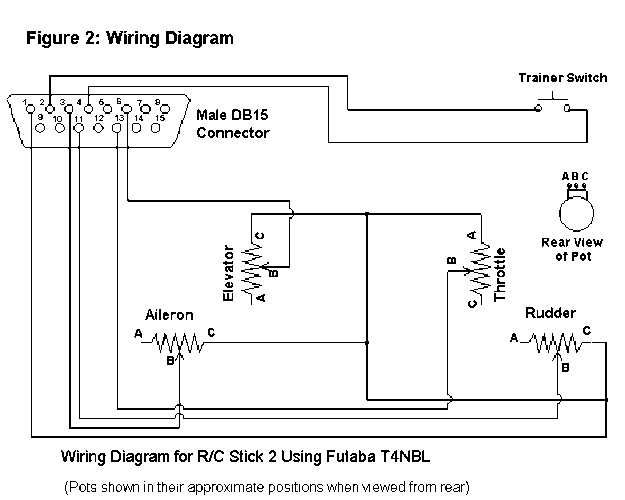
Now you can wire it. Pick out the ground wire (4) and +5 volt
wire (1). Even though there are other pins that carry ground and
voltage, we will not be using them as some of these pins are used
for Midi in/out connections on sound cards. Tape the other ground
and voltage wires up separate from each other so there's no
chance they can short out. THIS IS IMPORTANT. SHORTING GROUND
TO +5 VOLTS WILL FRY YOUR POWER SUPPLY! There are three wires
on the trainer switch. Use the VOM to find the two wires that
have continuity when the trainer switch is pressed and cut the
other one off. The ground connects to one of the remaining wires
(either one), and the wire from pin 2 on the joystick plug
connects to the other. Tape these connections up so there's no
chance they'll touch a +5 volt wire anywhere. The +5 volt line
will be pretty exposed as it'll be connected to all the pots, so
make sure there's no chance that a ground will ever touch the
back of a pot. Referring to the above diagram, the +5 volts will
be connected to contact C on each pot except the throttle, which
has it connected to contact A. Then each axis wire is connected
to contact B of the appropriate pot. Pin 3 on the joystick plug
goes to contact B on the ailerons pot, etc. When you're done, you
should have three wires left for the remaining three joystick
buttons. I didn't use them, but if you want, you can install
another momentary-on switch for button 2. Button 2 is used by
Flight Unlimited for turning your head while in cockpit view
(there are also keyboard shortcuts for this). Go on, look down,
you can see the rudder pedals! Again, connect another ground wire
to one side of the switch and pin 7 from the joystick plug to the
other. Tape up the remaining wires so they don't touch.
The only other thing remaining to be done is that you'll have to Dremel a couple of holes into the battery compartment to allow the backs of the rudder and aileron pots to protrude into it, in order to allow the back cover to fit. Double check to make sure no wires are touching and that you've connected everything properly. Then close it up, and we'll try it out.
Trying it Out:
DO NOT CONNECT THE R/C JOYSTICK TO THE COMPUTER YET! Turn
your computer on and let it boot to DOS. Cautiously, connect the
R/C Joystick to the game port while watching the monitor. IF
THE SCREEN GOES BLANK, DISCONNECT THE R/C JOYSTICK RIGHT AWAY!
You've got a short circuit! Somewhere in the box there's a ground
touching a voltage line. A brief short shouldn't damage anything,
and the computer should reboot as if you pressed the reset
button. Open it up and check everything.
If nothing untoward happened when you plugged it in, it's time to test it out. If you have a speed adjustable game port card installed, use it's utility program to set the card to a speed that gives you the most throw with a good center trim. If you have a joystick calibration utility that came with your game port card, use it to see if the R/C Joystick works. If running under Windows 95, use the Joystick Calibration icon in the control panel. If you have none of these, you can calibrate from within a game that shows you the stick positions after calibrating, such as Flight Unlimited or FS5 (FS5 shows the stick positions as small arrows on the instrument panel). Follow the utility's directions to set the trims for proper center, and confirm that you have a smooth response in each direction of each stick's axis. If there is one direction of an axis that has better resolution than the other, try turning the trim control for that axis in the bad direction and recalibrate. If your notch cutting was way off, you may have to open the case and turn the whole pot. It may take a little experimenting, but you should be able to find a trim position where you have a smooth response in both directions. Always recalibrate after changing the trim as this changes the center position. If you have to turn the pot very far in order for it to work, then you've probably cut the notch incorrectly, or accidently swapped the throttle pot for one of the others. Make certain that the sticks return to center, and that there is no "slop" in the center, which would indicate a bad fit between the pot's shaft and the joystick assembly.
That's it! Now go out and fly!
I hope you've found this article useful. I'll be happy to answer
any questions via E-Mail. Please let me know if you find any
typos or mistakes in this article so I can release a correction.
December 1995
Robert Osorio - The Flying Penguin
TheFlyingPenguin.com
10/26/96 Howard Sullivan (hlsulliv@ingr.com) was kind enough to
write in with a source for a smaller potentiometer like the ones
that were originally mounted in the transmitter (instead of those
bulkier Radio Shack pots). The supplier is Digi-Key Corporation,
a mail order electronics firm. The part is a CTS Series 270
1/4-watt, 1 Meg-ohms, Digi-Key Part No. CT2211-ND, CTS Part No.
270-XS8794. Price as of this date is $2.60 each.
Digi-Key Corporation
701 Brooks Avenue South
Thief River Falls, MN 56701-2757
Phone 1-800-344-4539
Fax 218-681-3380
Web Site: http://www.digikey.com/
Many thanks to Howard for this info!
![]()